Wednesday, June 4, 2008

Physical model of structural panels with UB rafters

Above are my autocad drawings, for the design development of the warehouse and office complex. Also included is the 1m x 1m detail that i focused on for my assignment.


Photograph of my model being taped up, ready to be painted.


White sealant has been used to try give the desired weilding effect between steel members.

Tuesday, June 3, 2008

Coen Pre Cast Factory site Visit

A visit (29/5/08) to the Coen Pre Cast fabrication factory in Moolap was organised through Andreas, the site manager. He took us on a guided tour of the factory, showing us all the stages and equipment for the panel completion.
Each panel has its own individual shop drawing, showing all the dimensions, cast in elements and other details required. It also specifies the panel weight, strength and reinforcement requirements. These drawings are used for the precise construction of the panels in the factory.

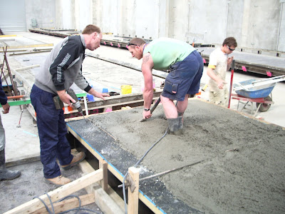
The workers must viabrate the concrete as it is poured using a 'wand'.

A ready mix truck will pour into the panel bed, covering the formwork, reinforced mesh and any additional inserts the cement. (Above)

Once the panel have been poured they are left in their panel beds over night, the next day they are moved to the storage racks in the warehouse. (Below)

Lifting inserts are casted into the panel and can be tied to the reinforced mesh. They allow for easy access to lift the panel safely.

Panels are lifted from their casting beds the day after they are poured. By this time they have reached a lifting strength on 25mpa and are then left placed in the rack for a minimum of 7 days to allow them to cure enough to take transport and erection stresses

Monday, June 2, 2008

Convenant College Gym Site Visit

We organised through Coen Pre Cast a site visit to Convenant College in Bell Post on the 28/5/08. Here they were erecting non structural pre cast panels and bolting them to the steel coloumns. The dano panel on the lean over trailer is being connected via the lifting inserts using 5-6 tonne olivetti clutches. This 25 tonne Franna crane can only be used for these types of panels, as other panels need to be rotated.


The Franna crane slowly lowers the panel into position while the two ground workers guide it using a burke (large crowbar).


Prior to any panels being lifted on site all the panel locations are marked out on the strip footings, and location pins are drilled in.


Once the structural panels are inplace, they need to be braced and propped using cast-in inserts to the panel and a deadman cast in-ground concrete anchoring brace (nominated on shop drawings).
This is a compliance/delivery document that is unique to each panel, it must have the panel id no., the date poured, the weight and strength of the panel. The crane driver can not lift a panel without this 'birth certificate'.


Saturday, May 31, 2008

Atex Steel Site visit

We contacted Atex Steel and organised a site visit on the 22/5/08, Adam the factory manager gave us a tour of the manufacturing equipment and materials. The fabrication factory is located at 2 Moon Street Moolap.

The physical size of the factory allows for long spanning steel universal beams to be fabricated under controlled conditions, with the assistance of the yellow overhead crane. This extensive fabrication in the factory under controlled conditions, reduces the time and labour required on site.


These are the connection that are to be welded to the UB, also pictured is the engineers drawings which specify the location of the holes that need to be drilled.


Once completely assembled the beams are treated with Inorganic zinc silicate primer paint, to protect the steel from exposed environments.

Thursday, May 22, 2008

Denny Lascelles Refurbishment 2

This is a photo of the coloumn connecting into the pad footing, as you can see the bracing plates are relatively large with multiple bolts. This was the standard connection method for all the columns throughout the building.
Above is the stairwell, the actual stairs are hollow core cast on site, and inconjuntion with the pre-cast concrete panels makes it almost inpenatrable by fire.Steel framework has been used for the university offices on the lower levels, it is a quick and effective way of errecting straight framework. Labour time is vastly reduced as a timber carpenter would have to deal with the natural inperfections of wood, therefore more labour intensive. The only downfall of steel framework is the difficulty of screwing/nailing into the studs.
This is the new top floor, even though it will not be used in the short term insulation and the fire services have been installed (red pipes). What appears to be different to the lower floors which were constructed in 1933 is the uninterupted floor space, there is not such a clutter of columns. Also the lower levels use a masonry for exterior walls while the newly constructed top level uses steel framework. (see photo below)

Denny Lascelles Refurbishment

The Denny Lascelles building was originally constructed in 1934, used as a wool store until 1992 when it was aqcuired by Deakin University.
The works will include a full 6 storey refurbishment, with only the bottom 2 levels being fully refurbished for university purposes, including offices and classrooms. The remaining levels will be fitted out with basic services, so they will be ready for future occupation.
Above is a photo of the exterior annex, with a precast concrete panel ceiling. The major columns are being temporarily supported by props until completed.
Above is a photo of the central atrium, allowing more natural light into a area that would otherwise be rather dark. What caught my eye is that there is no haunching on the beams.
The steel columns have been painted with a special white paint, which is supposed to be fire resistance for 2 hours, preventing any structural failure. The entire Denny Lascelles building was assessed by a fire engineer, this was required to get building permission by the council, especially due to the possible remaining flamible wool lindt.
What i thought was the most interesting fact from the site tour, was that the original floor ceiling heights were not sufficient for that required by the university for services etc. To retify this problem the construction team completely removed the first level floor, and then lowered each of the above floors to the obtained the desired clearance (except level 5). This was done by chaining sections of the floor to the above ceiling beam and lowering slowly to the required height. The picture above shows the old holes where the floor beams where bolted with cleats into the column. As this process reduced the building to only five levels it was decided to build a completely new level as the top floor.This is the new top floor level of the building, here you can see a suspended ceiling that is attached/hooked to the purlins above via metal rods.

Wednesday, May 7, 2008

Warehouse Under Construction 2

Roof to wall connections, with fly bracing giving additional support between columns.


Ridge connection with extensive haunching braced to 'c' purlins. There is safety mesh supporting the insulation, covered with Kliplok roofing, which you can see stack on the left ready to be fitted. Along with the red pipe, being the fire services.


The end wall panel shows the bracing from beams, which holds the individual smaller panels inplace. Along with the unfinished roof, hence the safety railing bolted to the 'c' purlins.